1
/
из
3
YanTechLab
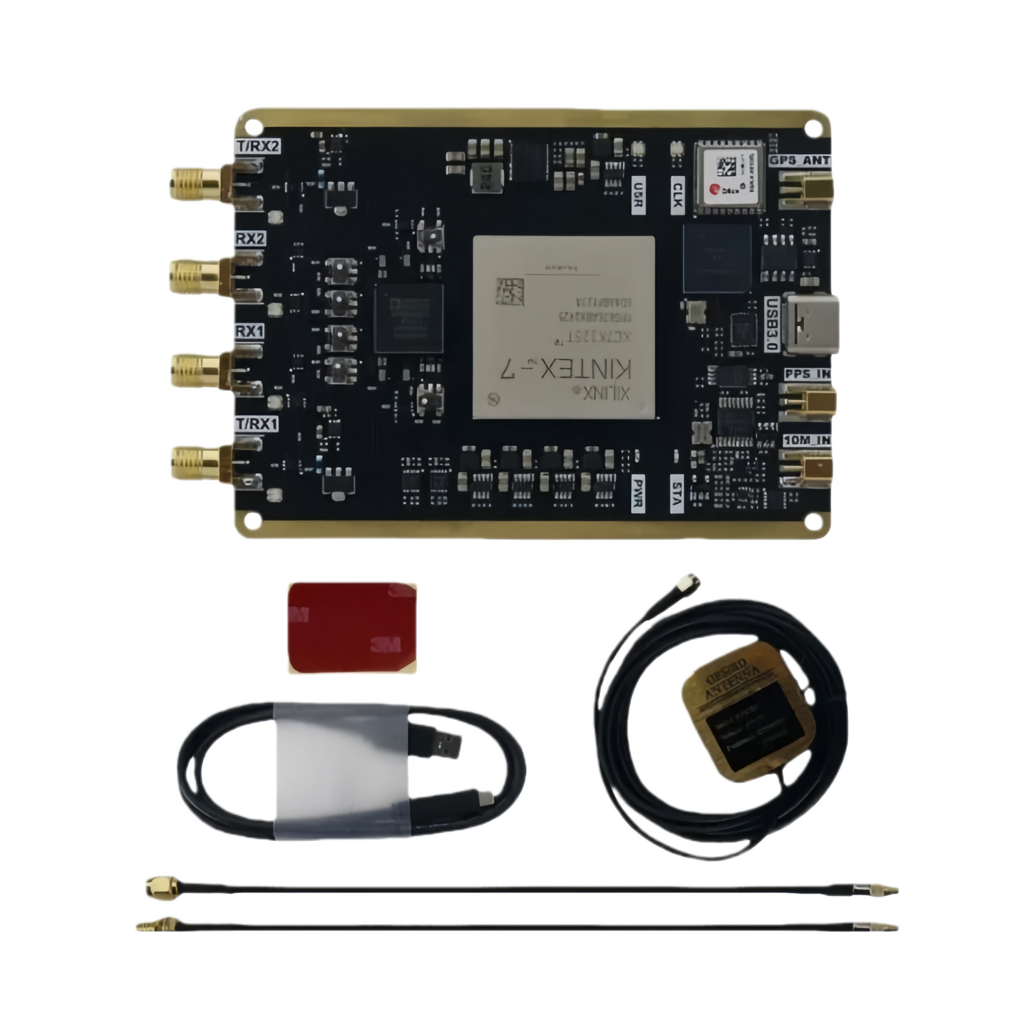
B210 USRP with XC7K325T + AD9361 and Onboard GPS Module for SDR Wireless Communication Development
B210 USRP with XC7K325T + AD9361 and Onboard GPS Module for SDR Wireless Communication Development
Обычная цена
$305.00 USD
Обычная цена
Цена со скидкой
$305.00 USD
Количество
Не удалось загрузить сведения о доступности самовывоза
Optimized USRP B210 SDR | Kintex-7 | USB 3.0 Type-C | GPS & PPS Support
This USRP B210-compatible SDR platform is an optimized and upgraded design based on the original reference hardware. It replaces the legacy Spartan-6 FPGA with a newer Kintex-7 (K7) series device, enabling full Vivado development support while maintaining compatibility with official B210 functionality.
Functional Overview
| FPGA Architecture | Upgraded from Spartan-6 to Kintex-7 , supporting Xilinx Vivado toolchain and modern IP cores. |
|---|---|
| USB Interface | USB 3.0 Type-C interface with a maximum real-time data bandwidth of 56 MHz . |
| RF Front-End | Identical RF front-end architecture to the official B210, using band-segmented RF design . RF traces are simulation-optimized for signal integrity. |
| Reference Inputs | Supports PPS and 10 MHz external reference inputs. |
| GPS Module | Onboard GPS module integrated, capable of replacing external PPS input. |
| GPSDO Support | GPSDO socket removed to reduce size and simplify the design. |
| Mechanical Size | Compact form factor: 70 × 97 × 11.5 mm . |
Usage Notes & Differences from Official B210
| FPGA Bitstream | Before use, replace the PC-side usrp_b210_fpga.bin file with the provided version. |
|---|---|
| GPSDO Module | External GPSDO modules are not supported . |
| PPS Priority | The onboard GPS PPS signal has higher priority than the external PPS input. When GPS is locked, the external PPS input is disabled. |
Interface Description
| GPS | GPS antenna input, MMCX connector |
|---|---|
| USB | USB 3.0 data connection to host, Type-C connector |
| PPS | External PPS input, MMCX connector |
| 10 MHz | 10 MHz reference clock input, MMCX connector |
| TRX1 | TX or RX Channel 1, SMA connector |
| RX1 | RX Channel 1, SMA connector |
| RX2 | RX Channel 2, SMA connector |
| TRX2 | TX or RX Channel 2, SMA connector |
| FPC Connector | JTAG debug interface and extended GPIO |
| POWER LED | Power indicator LED, solid red when powered |
| STATUS LED | Status LED, blue after firmware is loaded |
| CLK LED | PPS indicator LED, red flashing synchronized to selected PPS source |
| USER LED | Reserved, user-defined |
| TRX1 LED | TX/RX indicator, red during TX, blue during RX |
| RX1 LED | RX indicator, blue during reception |
| RX2 LED | RX indicator, blue during reception |
| TRX2 LED | TX/RX indicator, red during TX, blue during RX |
Documentation & Resources
Complete documentation and support materials are available via:
t.me/YanTechLab
Share
No reviews